
Pseudospectral methods
A pseudospectral method represents each state by a polynomial through values at special points called nodes, then enforces the dynamics as equalities at those nodes. This page walks through the LGL (Legendre–Gauss–Lobatto) method used by OpenGoddard.
- Map time to . Use the same reference interval for any phase duration.
- Place the nodes. Include both endpoints and specially chosen interior points.
- Interpolate the state. Treat the node values as unknowns.
- Differentiate with a matrix. Polynomial derivatives are linear combinations of node values.
- Enforce the dynamics. Match the polynomial slope to the dynamics at every node.
- Integrate with a weighted sum. Approximate the running cost by quadrature.
- Solve the NLP. Optimize the node values and phase times with SLSQP.
1. Normalize time
Section titled “1. Normalize time”Map linearly to :
Thus . The final time can remain an optimization variable.
2. LGL nodes
Section titled “2. LGL nodes”For nodes , use:
- Endpoints and .
- The roots of in the interior, where is a Legendre polynomial.
For , the nodes are approximately . They cluster near the endpoints.
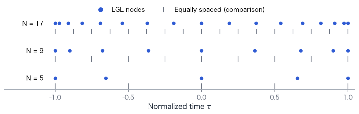
Why not equally spaced points?
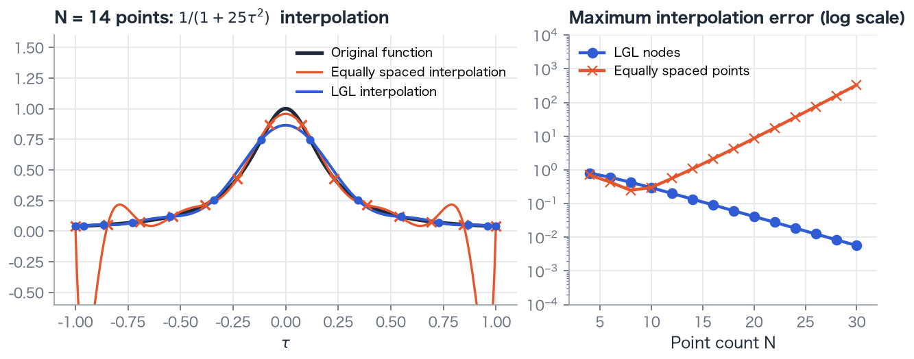
Section titled “Why not equally spaced points?”High-degree interpolation on equally spaced points can oscillate strongly near the endpoints (Runge’s phenomenon). Adding more points can make the approximation worse. LGL nodes suppress this behavior in the example below and yield rapidly decreasing error.
3. Polynomial representation
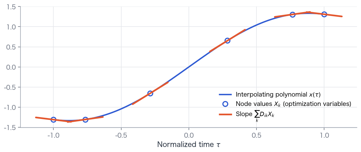
Section titled “3. Polynomial representation”The node values are optimization variables. Interpolate them with a polynomial of degree :
The Lagrange basis polynomial is 1 at and 0 at all other nodes. The interpolant therefore takes exactly the value at node . Controls are represented by node values in the same way.
4. Differentiation matrix
Section titled “4. Differentiation matrix”The interpolant’s derivative at a node is an exact linear combination of its node values:
The differentiation matrix depends only on node locations and is computed once.
A small example: N = 3
Section titled “A small example: N = 3”With nodes ,
For , the node values are and
These are exactly the values of at the nodes. A quadratic is represented exactly by three points, so its derivative is exact too.
5. Enforce the dynamics
Section titled “5. Enforce the dynamics”Replace by one equality per node, including the time normalization factor:
The left side is the polynomial slope; the right side is the slope required by the dynamics. Their difference is the defect, which must vanish. Repeat the equations for each state.
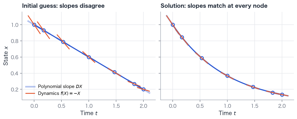
This is the core of direct collocation: handle the differential equation as a set of algebraic slope-matching equations. The optimizer improves the objective while finding node values with zero defects.
6. Quadrature
Section titled “6. Quadrature”Use Gauss–Lobatto quadrature for the running cost:
The weights depend only on the nodes. This rule is exact for polynomials of degree at most . For , : Simpson’s rule.
7. Solve the nonlinear program
Section titled “7. Solve the nonlinear program”Collect the unknowns in
The problem becomes
Because LGL includes the endpoints, boundary conditions apply directly to and . For Example 07, three states, one control, and 50 nodes give unknowns and 150 defect equalities. This scale is practical for SciPy’s SLSQP.
You provide only , , , , and . The library computes nodes, differentiation matrices, defects, quadrature, and the NLP.
Multiple phases
Section titled “Multiple phases”A single polynomial cannot accurately represent abrupt thrust switches or mass jumps without oscillating nearby. Split time into phases, each with its own nodes and interpolant, and impose linkage conditions at the knots:
- Continuous states: (automatic in OpenGoddard).
- Discontinuous states: write the jump yourself, for example .
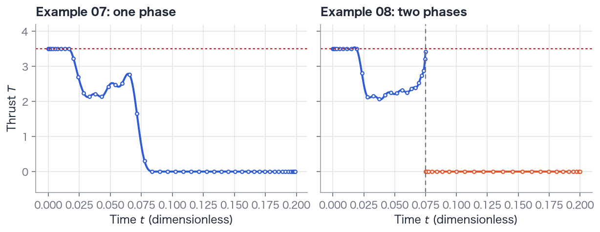
Controls may be discontinuous at knots. Knot times may also be optimized.
Checking accuracy
Section titled “Checking accuracy”A successful solver status means that the discretized NLP has been solved. Check whether the trajectory accurately represents the original problem by increasing the node count and comparing results.
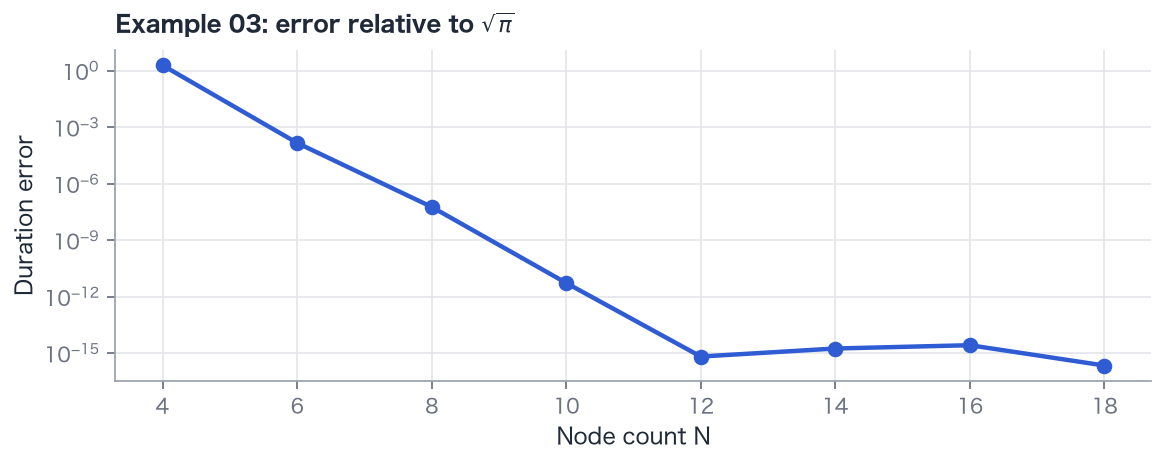
OpenGoddard also provides estimate_error to estimate between-node residuals and solve_adaptive to refine inaccurate phases automatically
(writing a problem).
References
Section titled “References”Theory and numerical methods
Section titled “Theory and numerical methods”- F. Fahroo and I. M. Ross, “Costate Estimation by a Legendre Pseudospectral Method”, J. Guidance, Control, and Dynamics, 24(2), 2001. doi:10.2514/2.4709
- I. M. Ross and F. Fahroo, “Pseudospectral Knotting Methods for Solving Nonsmooth Optimal Control Problems”, J. Guidance, Control, and Dynamics, 27(3), 2004. doi:10.2514/1.3426
- Q. Gong, F. Fahroo, and I. M. Ross, “Spectral Algorithm for Pseudospectral Methods in Optimal Control”, J. Guidance, Control, and Dynamics, 31(3), 2008. doi:10.2514/1.32908
- A. V. Rao et al., “Algorithm 902: GPOPS, A MATLAB Software for Solving Multiple-Phase Optimal Control Problems Using the Gauss Pseudospectral Method”, ACM Transactions on Mathematical Software, 37(2), Article 22, 2010. doi:10.1145/1731022.1731032
- J. T. Betts, Practical Methods for Optimal Control and Estimation Using Nonlinear Programming, 2nd ed., SIAM, 2010. A standard reference on direct methods.
Launch vehicle trajectory optimization
Section titled “Launch vehicle trajectory optimization”- I. Ross, C. D’Souza, F. Fahroo, and J. Ross, “A Fast Approach to Multi-Stage Launch Vehicle Trajectory Optimization”, AIAA Guidance, Navigation, and Control Conference and Exhibit, 2003. doi:10.2514/6.2003-5639
- J. R. Rea, “A Legendre Pseudospectral Method for Rapid Optimization of Launch Vehicle Trajectories”, MIT, 2001. MIT repository
Japanese-language references
Section titled “Japanese-language references”- Masanori Harada, study of accurate quadrature weights for Jacobi pseudospectral optimization, Transactions of the JSME, Series C, 77(784), pp. 4458–4467, 2011. doi:10.1299/kikaic.77.4458
- Masanori Harada, estimation of dual variables in Jacobi pseudospectral optimal control, Transactions of SICE, 49(8), pp. 808–815, 2013. doi:10.9746/sicetr.49.808
- Masanori Harada, trajectory optimization using high-order Gauss–Lobatto weights in the Jacobi pseudospectral method, Transactions of the JSME, Series C, 73(728), pp. 1075–1080, 2007. doi:10.1299/kikaic.73.1075
- Takahiro Fujikawa, Takeshi Tsuchiya, and Hideyuki Taguchi, hypersonic flight testing using a sounding rocket, part 2: trajectory study, Space Transportation Symposium FY2012 proceedings, 2013. JAXA repository