
13. Two-stage orbital insertion in polar coordinates
Most launch vehicles discard an empty first stage instead of carrying its tanks and engines to orbit. Add stage separation to the two-dimensional ascent in Example 12 and optimize when to separate and how each stage should thrust.
| Item | Definition |
|---|---|
| States | Radius , angle , radial and tangential velocities , mass |
| Controls | Thrust components |
| Objective | Maximize second-stage mass at orbital insertion |
| Phases | Two phases, 20 nodes each; free separation and final times |
| New concepts | Two-dimensional staging and phase-dependent vehicle parameters |
Situation
Section titled “Situation”Launch mass is 20 t, including a 1 t second stage. First-phase mass cannot fall below 2 t. At separation, the second stage starts at 1 t; the discarded mass is the pre-separation mass minus 1 t.
The second-stage engine has higher specific impulse (350 s versus 300 s) but much lower thrust (14.7 kN versus 294 kN). The target is a 500 km circular orbit. Earth rotation is neglected, and acceleration is limited to 8 G.
Formulation
Section titled “Formulation”Coordinates
Section titled “Coordinates”Use the polar coordinates of Example 12. Altitude is , downrange distance is , and radial and tangential components are local vertical and horizontal components.
Phases and linkage
Section titled “Phases and linkage”At the optimized separation time , position and velocity are continuous while mass resets:
Disable automatic mass continuity and impose the linkage explicitly (linking phases).
Dynamics
Section titled “Dynamics”For stage ,
The polar velocity terms express centrifugal acceleration and conservation of angular momentum.
Boundary conditions
Section titled “Boundary conditions”Target speed is about 7616.6 m/s. Final angle and time are free.
Constraints
Section titled “Constraints”Unlike Example 12, thrust components can be negative, allowing downward and backward thrust. The second-stage mass lower bound is its 200 kg dry mass. Acceleration excludes gravity.
Objective and parameters
Section titled “Objective and parameters”| Parameter | Stage 1 | Stage 2 |
|---|---|---|
| Phase-start mass | 20 t | 1 t |
| Mass lower bound | 2 t | 200 kg |
| 0.2, 3.14 m² | 0.2, 3.14 m² | |
| 300 s | 350 s | |
| 294.2 kN | 14.7 kN |
Use km, m/s², and m³/s². Units follow Example 12 with mass scaled by 20 t.
Initial guess
Section titled “Initial guess”Use times s. Radius and angle rise cubically to target altitude and 25°. Radial velocity is zero; tangential velocity increases linearly to target. Mass decreases cubically from 20 to 2 t and from 1 t to 200 kg in the respective phases. Radial and tangential thrust decrease cubically from 0.9 and 0.1 times each stage’s maximum to zero.
Results
Section titled “Results”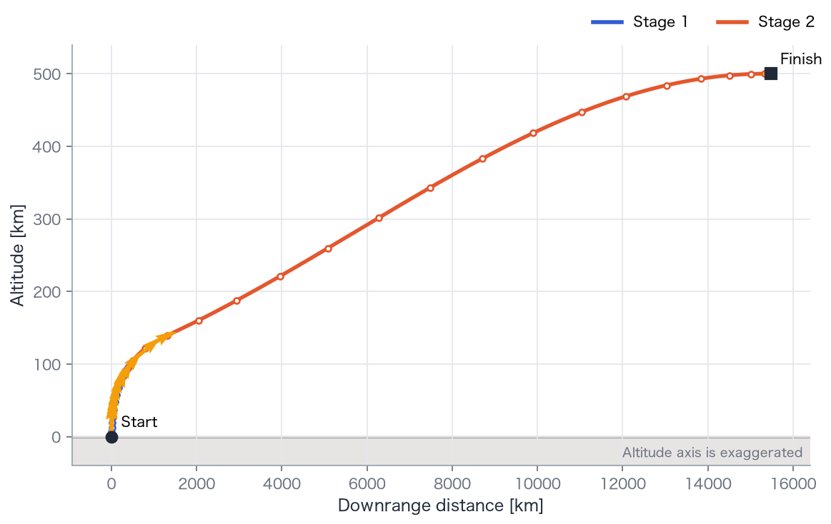
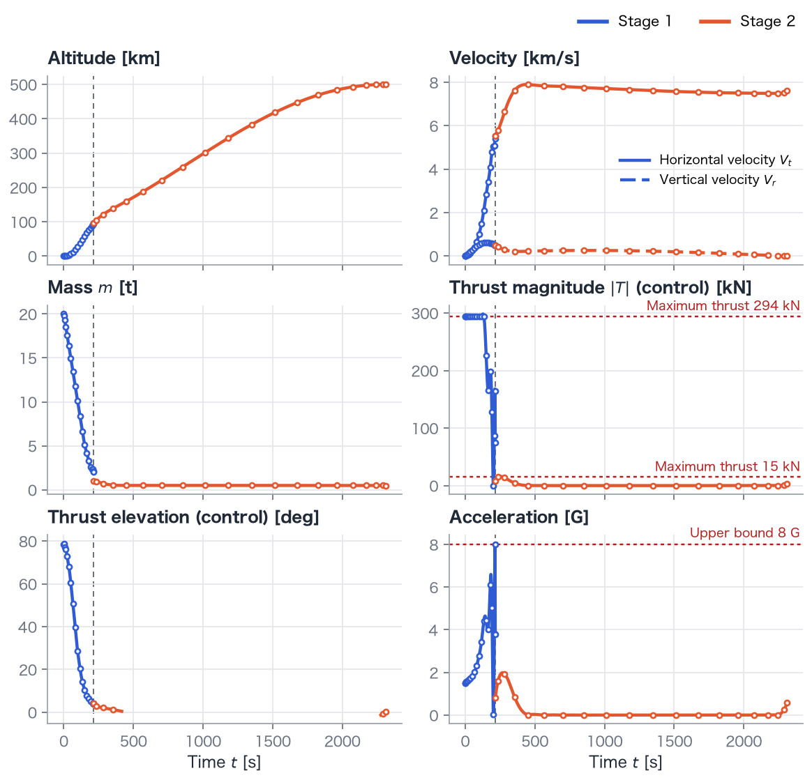
- Separation occurs at 215.5 s, with mass 2,000 kg at the phase-1 lower bound.
- Tangential speed at separation is 5,536 m/s, so stage 1 supplies much of the orbital speed.
- Stage 2 burns until about 2,312 s, coasts, then burns again from about — to 2,312 s.
- Delivered mass is 476.5 kg; subtracting 200 kg of dry structure leaves capacity for payload and remaining propellant.
- Final altitude and speed are 500.0 km and 7,616.6 m/s.
- Maximum node acceleration reaches 8.00 G.
Explanation
Section titled “Explanation”Throttle near first-stage burnout
Section titled “Throttle near first-stage burnout”Applying 294 kN to a 2 t vehicle would produce about 15 G, exceeding the 8 G limit. The first stage must throttle near separation. With few nodes, its interpolated thrust oscillates, and acceleration can exceed 8 G between nodes even though the node constraints hold.
A long coast and Hohmann-like transfer
Section titled “A long coast and Hohmann-like transfer”The second stage accelerates near 100–150 km altitude, then coasts around Earth to 500 km apogee. Insertion occurs 15,476 km downrange. A final burn circularizes the orbit. This resembles a Hohmann transfer: accelerate low, coast outward, and circularize at apogee. The low-thrust upper stage produces longer burns, with a coast exceeding 30 minutes in this solution.
Why staging helps
Section titled “Why staging helps”Discarding roughly 1 t of first-stage structure leaves a lighter vehicle for the second-stage engine, which is also more efficient in near-vacuum conditions. Unlike Example 12’s very optimistic 1% dry mass, staging permits less extreme structural assumptions.
Try it
Section titled “Try it”- Raise stage-2
Ispfrom 350 to 450 and compare delivered mass and burn duration. - Relax
MaxGfrom 8 to 15 and inspect throttling and oscillations near separation. - Increase
[20, 20]to[30, 30]nodes and compare thrust oscillation.
uv run python examples/13_rocket_ascent_polar_tsto.py