
14. Two-stage orbital insertion from Taiki
Replace Example 13’s simplified parameters with a small launch vehicle, tabulated atmosphere and drag, an initial velocity from Earth rotation, and engine performance that changes with ambient pressure. Which parts of the optimal trajectory change, and which remain similar?
| Item | Definition |
|---|---|
| States | Radius , angle , radial and tangential velocities , mass |
| Controls | Thrust components |
| Objective | Maximize second-stage mass at insertion |
| Phases | Two phases, 20 and 30 nodes; free separation and final times |
| New concepts | Tabulated models, rotational initial velocity, pressure-dependent thrust and specific impulse |
Situation
Section titled “Situation”Launch a 1.8 m diameter rocket from Taiki, Hokkaido (about 42.5° N), carrying a 100 kg payload to a 561 km circular orbit at 96.7° inclination. This inclination is slightly retrograde, a type used for Sun-synchronous Earth-observation orbits. Compared with Example 13, the model adds:
- Atmosphere tables: linearly interpolated density, pressure, and sound speed from the US Standard Atmosphere between 0 and 86 km. Density and pressure are zero above 86 km.
- Mach-dependent drag: a coefficient table with a transonic peak.
- Earth rotation: the launch site already has velocity in an inertial frame.
- Ambient-pressure corrections: thrust and specific impulse improve as pressure decreases.
Formulation
Section titled “Formulation”Coordinates
Section titled “Coordinates”Use the polar coordinates of Example 12. Velocities are measured in a frame that does not rotate with Earth. This is a planar approximation, rather than a full three-dimensional inclination model.
Phases and linkage
Section titled “Phases and linkage”At optimized separation time ,
Position and velocity remain continuous; mass resets to the initial second-stage mass.
Dynamics
Section titled “Dynamics”The centrifugal and angular-momentum terms are unchanged from Example 13. The same defines gravity and target circular speed.
Atmosphere and drag
Section titled “Atmosphere and drag”Density , pressure , and sound speed are interpolated from tables:
The drag coefficient is about 0.28 at subsonic speeds, peaks near 0.68 around Mach 1.2–1.4, and falls to about 0.34 near Mach 4.5. Values outside the table are linearly extrapolated. The 1.8 m diameter gives area m².
Pressure-dependent thrust and specific impulse
Section titled “Pressure-dependent thrust and specific impulse”Reference performance is sea-level for stage 1 (261 s) and vacuum for stage 2 (322 s). With nozzle exit areas and launch altitude m,
Rocket.delta_thrust computes these corrections. Specific impulse changes consistently:
The thrust limit becomes . At that limit, mass flow remains regardless of altitude: lower external pressure gives more thrust at the same propellant flow. For stage 1, the vacuum correction adds about 41.6 kN and raises specific impulse to about 294 s. Stage 2 operates in nearly zero pressure, so its correction is small.
Earth rotation and initial velocity
Section titled “Earth rotation and initial velocity”At latitude , the launch site’s eastward speed is
For orbit inclination , launch azimuth satisfies . Projecting rotation into the modeled direction gives
Latitude cancels in this projection. The retrograde target requires a slightly westward azimuth, about −9° from north, so rotation opposes the modeled flight direction. The cross-plane component, about 338 m/s, is omitted by the two-dimensional model. Drag uses the modeled velocity directly; atmospheric co-rotation is not included.
Boundary conditions
Section titled “Boundary conditions”Stage masses are kg and kg including payload, giving launch mass 14566.7 kg. Target speed is about 7583.0 m/s.
Constraints
Section titled “Constraints”The mass lower bounds are 2866.7 kg for phase 1 and 320 kg (220 kg structure + 100 kg payload) for phase 2. Thrust direction is free. Dynamic pressure measures aerodynamic loading; its 500 kPa limit is generous. Acceleration excludes gravity.
Objective and parameters
Section titled “Objective and parameters”| Parameter | Stage 1 | Stage 2 |
|---|---|---|
| Dry mass | 1300 kg | 220 kg |
| Structural fraction | 10% | 15% |
| Wet stage mass, excluding payload | 13000 kg | 1466.7 kg |
| Payload | — | 100 kg |
| Reference maximum thrust | 33.3 tf (326.6 kN) | 4.2 tf (41.2 kN) |
| Reference specific impulse | 261 s, sea level | 322 s, vacuum |
| Engines / nozzle expansion ratio | 9 / 20 | 1 / 140 |
| Total nozzle exit area | 0.411 m² | 0.319 m² |
The throat diameter is 53.9 mm. Use km, m/s², m³/s², latitude 42.506°, rotation rate rad/s, and inclination 96.7°. Scaling follows Examples 12–13 with mass unit 13000 kg.
Initial guess
Section titled “Initial guess”Use times s. Radius and angle increase cubically to target altitude and 25°. Radial velocity is zero; tangential velocity grows linearly from to target. Mass decreases cubically to the phase lower bounds. Thrust components decrease cubically from radially and tangentially to zero.
Results
Section titled “Results”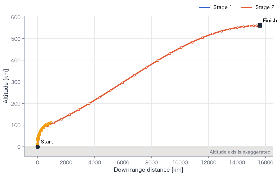
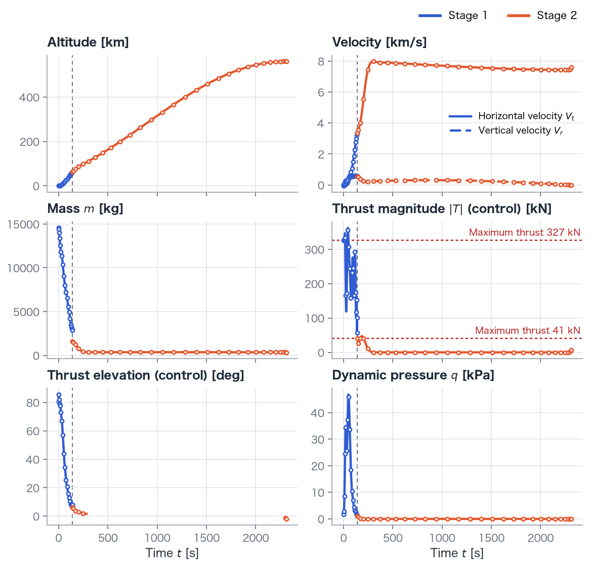
- Separation: 139.0 s, at mass 2,866.7 kg and tangential speed 3,356 m/s. The first-stage mass lower bound is active.
- The upper stage burns until about 293 s, then coasts, and burns again from 2,302 to 2,311 s.
- Delivered mass: 342.5 kg, slightly above 320 kg. The 100 kg payload is carried with some propellant remaining.
- Final altitude: 561.0 km; speed: 7,583.0 m/s.
- Maximum node dynamic pressure: 45.9 kPa; acceleration: 6.99 G. Both limits are inactive.
Explanation
Section titled “Explanation”The trajectory structure remains similar
Section titled “The trajectory structure remains similar”The vehicle rises, turns horizontal, accelerates with the upper stage, coasts to target apogee, and circularizes. More detailed atmosphere and engine models change the numbers while retaining this Hohmann-like structure. Simple models help identify the pattern; detailed ones refine the estimates.
What changes with a detailed model?
Section titled “What changes with a detailed model?”- Drag coefficient increases about 2.4-fold near sonic speed. Dynamic pressure peaks early, then falls with density.
- Rotation costs about 54 m/s in this westward projection; an eastward target could benefit instead.
- First-stage thrust and specific impulse increase with altitude. Nodes above the reference red thrust line can therefore remain feasible.
First-stage thrust zigzags
Section titled “First-stage thrust zigzags”The solver reports convergence, but first-stage thrust varies strongly between nodes. Final mass appears relatively insensitive to the detailed timing of first-stage thrust, so do not interpret each oscillation as a meaningful flight feature. More nodes or thrust-rate constraints can improve the representation.
Try it
Section titled “Try it”- Lower
MaxQfrom 500000 to 30000 Pa. Inspect the clipped dynamic-pressure peak and reduction in final mass. - Change
inclinationfrom 96.7° to 45°. The projected rotational initial speed becomes positive; compare delivered mass. - Raise
Mpayloadfrom 100 to 150 kg and check whether final mass still exceeds dry mass plus payload.
uv run python examples/14_polar_tsto_taiki.py